Experimental platforms at the Dynamics and Control Systems Laboratory for validating spacecraft
guidance, navigation, and control algorithms under space-like laboratory conditions.
ASTROS
Autonomous Spacecraft Testing of Robotic Operations in Space
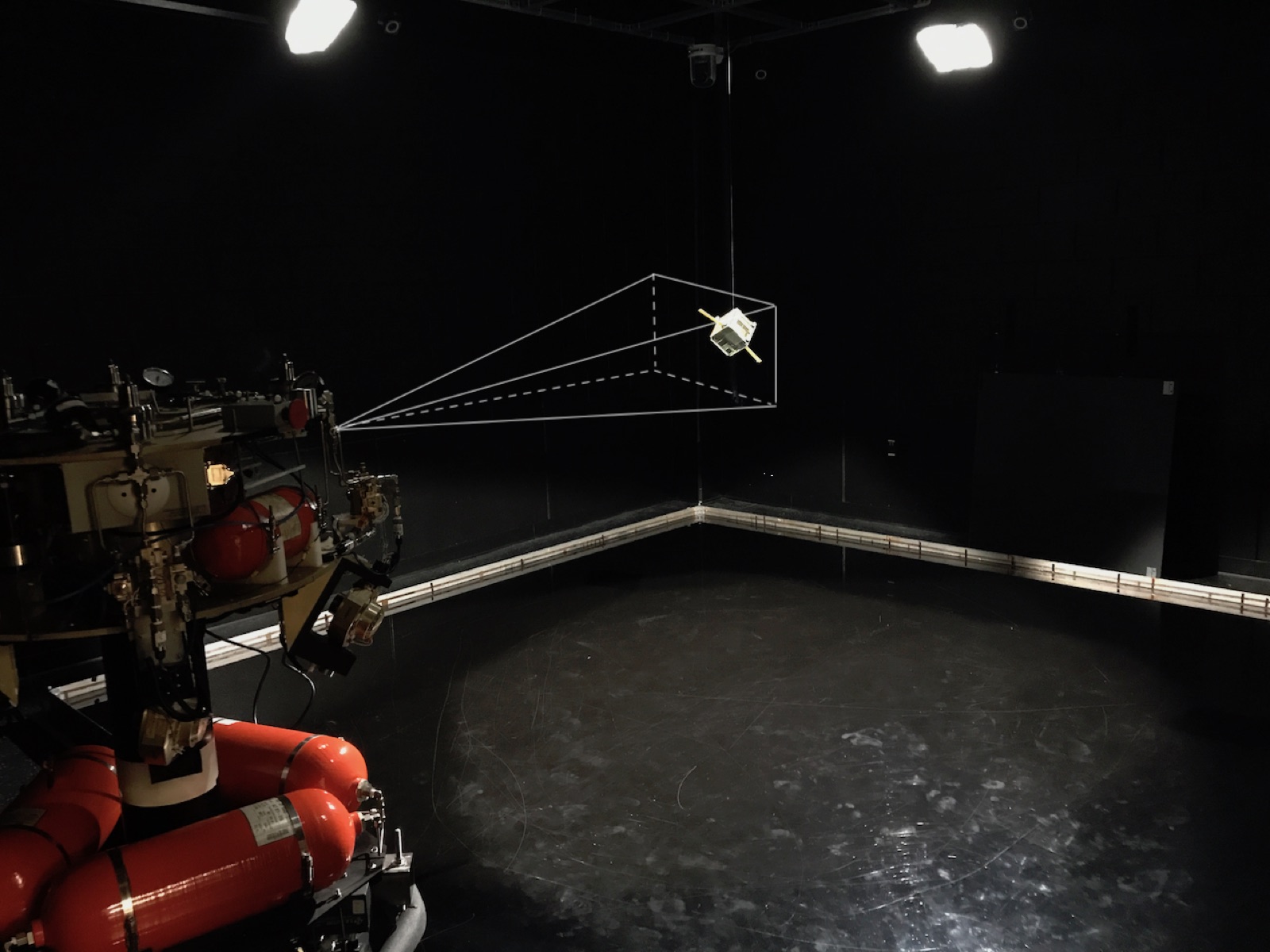
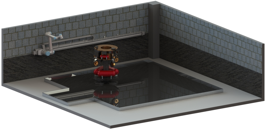
The ASTROS test arena, with a suspended CubeSat target and the platform camera field of view.
Autonomous proximity operations — including timely, on-demand, on-orbit servicing and refueling of space
assets — are an enabling capability for both civilian and military space, advancing information gathering,
asset upgrading, and maintenance. Such activities belong to the larger realm of space robotics, which applies
modern autonomous robotics methods to difficult and sensitive tasks while reducing reliance on
human-in-the-loop interference from the ground segment.
ASTROS is a 5-DoF spacecraft simulator and frictionless-motion experimental platform. Its objective is to
validate and evaluate the performance of guidance, navigation, and control (GNC) algorithms designed for
in-space rendezvous, using dedicated hardware under space-like test conditions that reproduce the motion of a
spacecraft under the authority of an onboard GNC algorithm.
The facility comprises a test arena where experiments are performed and a control room from which users
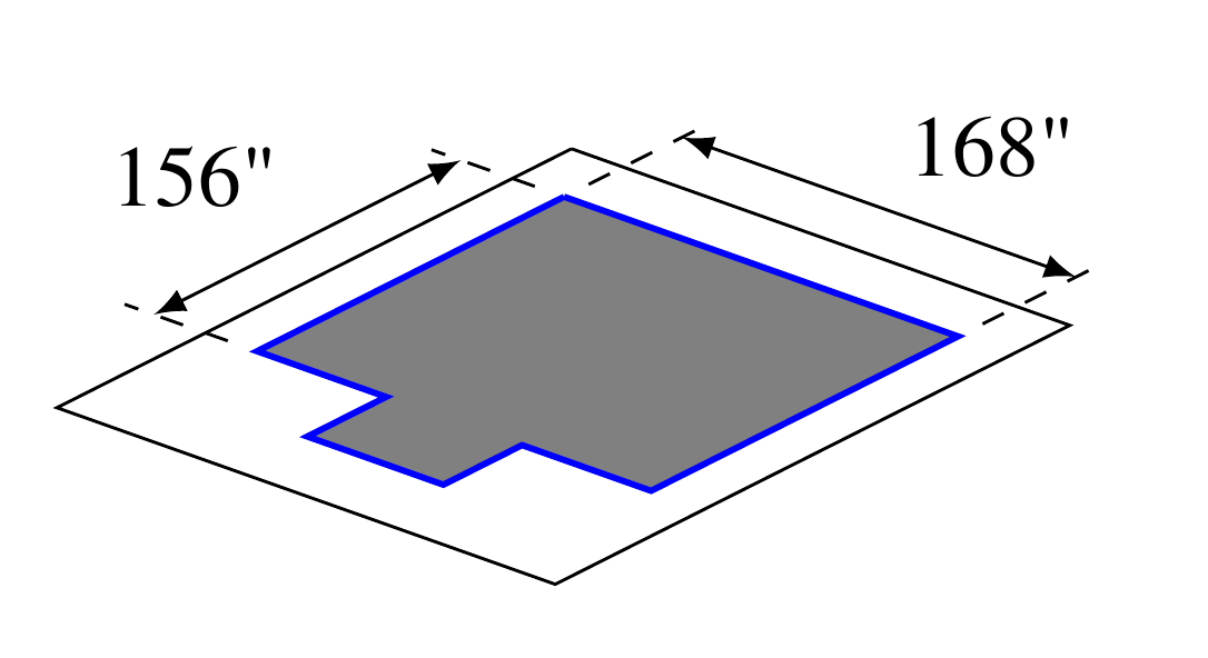
monitor and command execution via a development computer. The arena is a 4 m × 4 m (14 ft × 14 ft) flat epoxy
floor over which experimental platforms hover without friction, with dedicated lights on scaffolding to mimic
space-like lighting conditions in the visible spectrum.
Test arena dimensions.
Platform Architecture
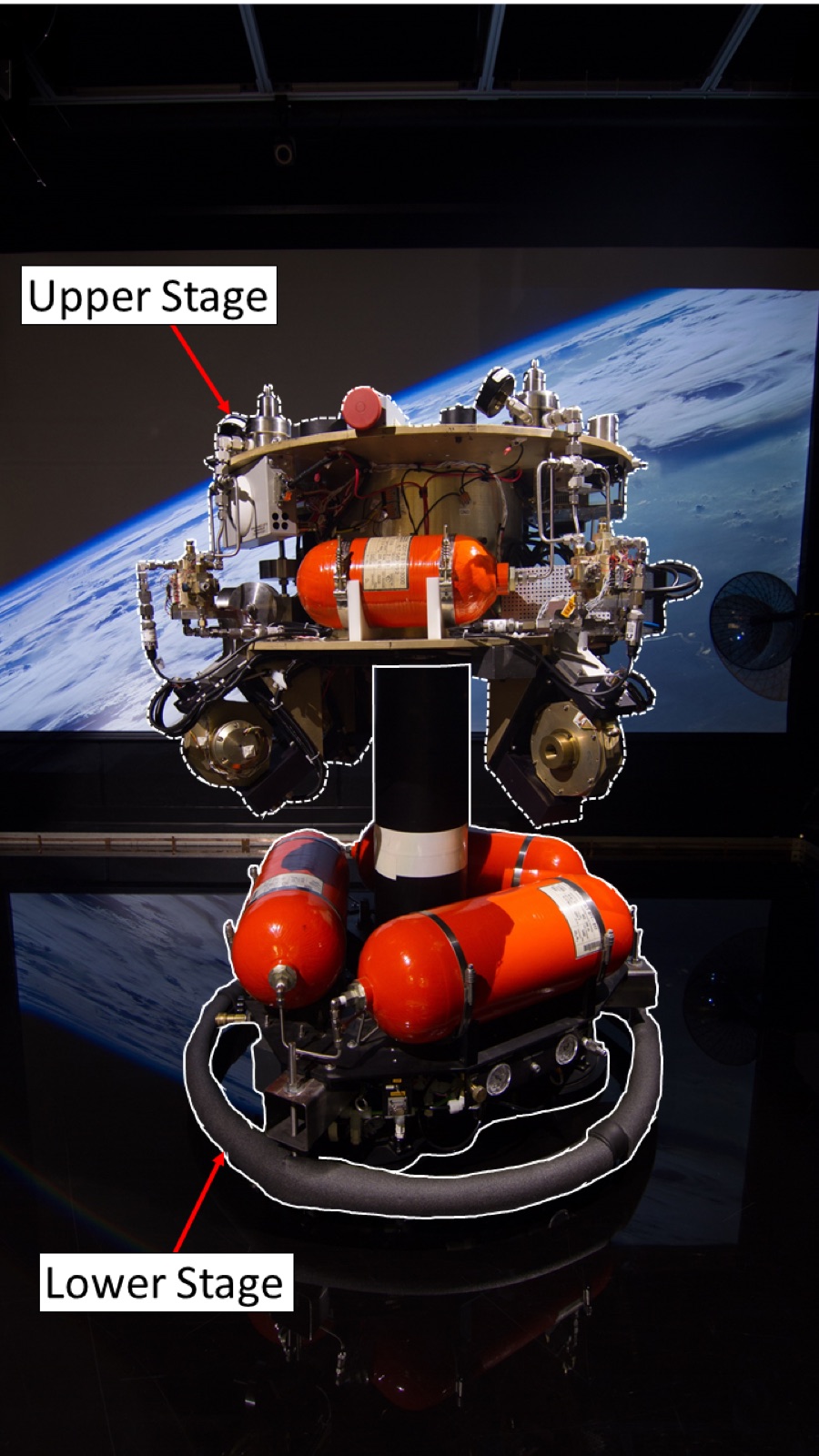
The test platform comprises two segments, the lower and upper stages, which can be operated in a pure rotation
mode, a fully connected mode, or a full 5-DoF mode, depending on which segments are levitated.
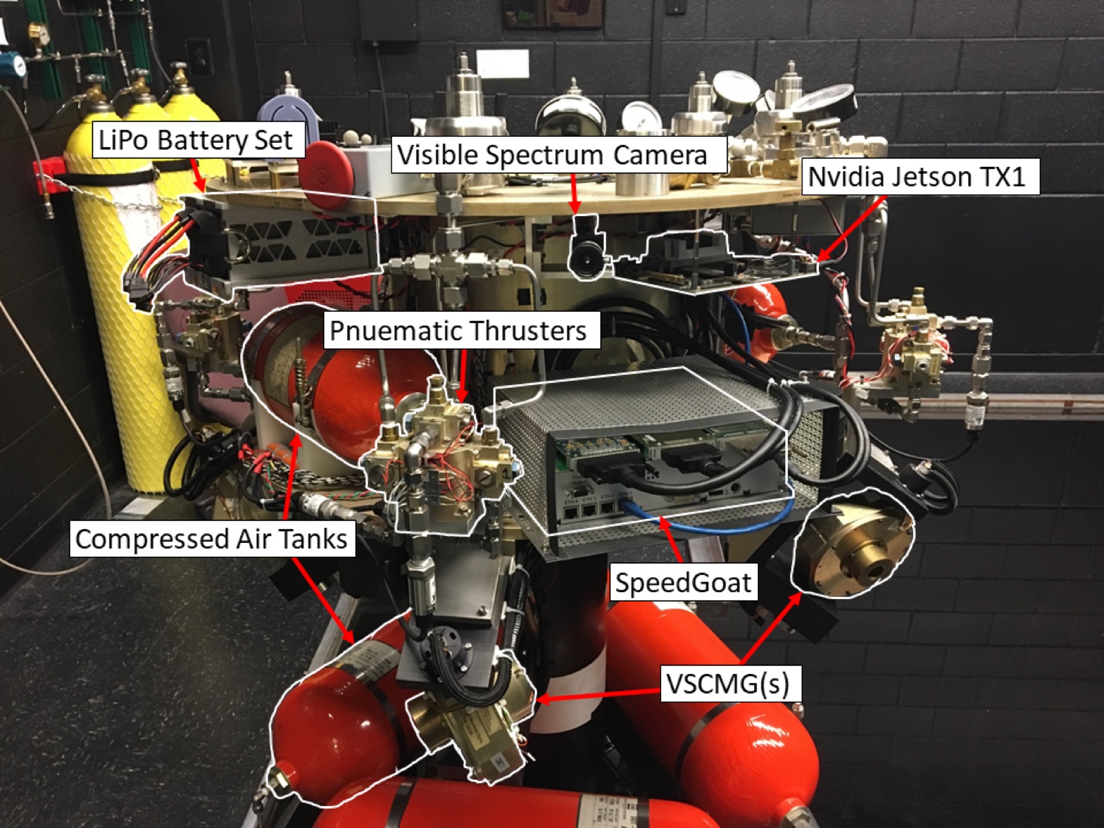
The two-stage platform.
The lower stage carries four high-pressure air tanks storing up to 3300 psig, three linear
air bearings, and a hemispherical air bearing. The linear bearings levitate the 450 lb platform off the epoxy
floor by less than the width of a human hair, providing two degrees of freedom in translation across the arena
and one in rotation. The hemispherical bearing at the top of the lower stage presents a near-perfect spherical
surface, which in turn levitates the upper stage on high-pressure air.
The upper stage sits on that bearing through a near-perfect spherical cup and, once
levitated, contributes the remaining three rotational degrees of freedom. It also houses the essential sensing,
computation, and actuation systems. Twelve pressurized-air thrusters in a 3-3-3-3 configuration each provide
5 lbf, modulated by a 10 Hz pulse-width modulation scheme; actuated individually or in groups, they impart the
linear and angular momentum changes required to follow a reference trajectory. Two further air tanks store the
energy for thruster actuation, fed through a high-pressure regulation system.
A set of four variable-speed control moment gyros (VSCMGs) in a pyramid configuration provides additional
torque by momentum exchange, reducing thruster use for controlling upper-stage rotation. Using two motors
driven by dedicated Roboteq DC motor drivers, each VSCMG can generate gimbal velocity — a change in the
direction of angular momentum — and wheel acceleration, a change in its magnitude. Four lithium-polymer
batteries supply the electrical energy to actuate the VSCMGs and the thruster solenoids. The upper stage
further comprises power conditioning and distribution units (PCDUs), auto-balancing linear stage motors,
onboard computers, communication interfaces, and dedicated sensors.
Sensing and Computing
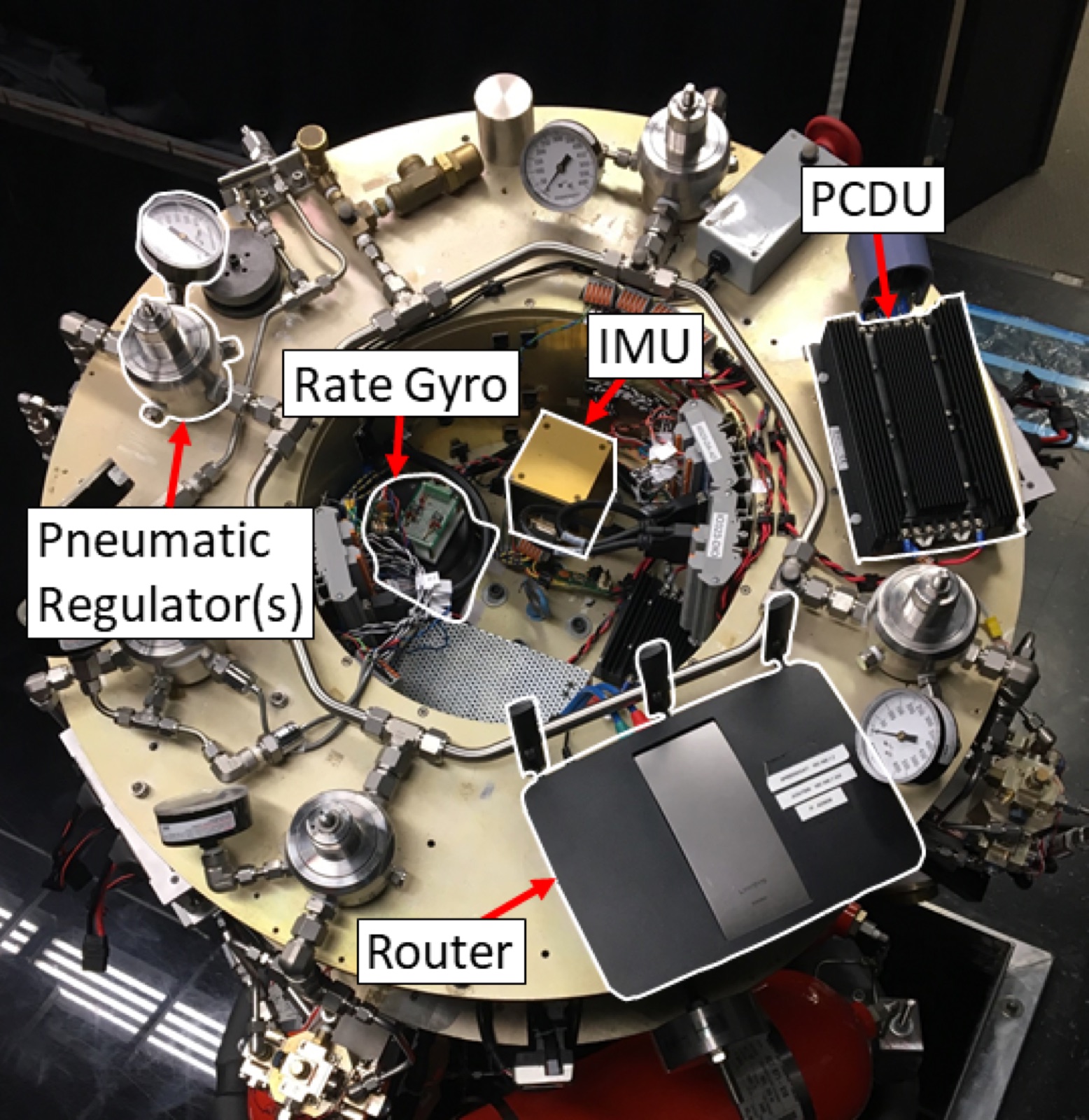
The sensor suite includes a three-axis inertial measurement unit (IMU), a rate gyro, and a two-axis
inclinometer, together with a visible-spectrum camera, an infra-red camera (projected), and a time-of-flight
camera. These allow perception algorithms to be tested on the platform directly using an Nvidia Jetson TX1
micro-computer, which also supports applications requiring multi-sensor fusion or heavy image processing.
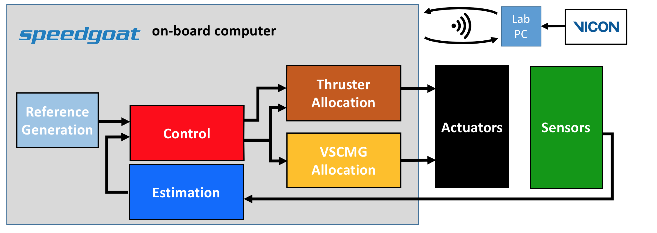
GNC algorithms are compiled and executed on a SpeedGoat MATLAB/Simulink real-time target computer housed in the
upper stage. Interfacing with the target over WiFi, users prototype algorithms in the familiar Simulink
environment on the development computer, then remotely upload, compile, and execute maneuvers on the platform.
Onboard GNC architecture, with the external VICON motion-capture ground truth.
Robotic Manipulator
The facility also includes a Universal Robots U10e Series six-axis robotic arm, with a 1300 mm reach
and a 10 kg payload. The arm is mounted on a sliding base that adds a seventh, linear axis along the
edge of the arena. The resulting seven-degree-of-freedom system allows manipulation tasks to be
performed between the arm and the ASTROS platform.
The robotic arm on its linear rail alongside the ASTROS platform.
Specifications
Test arena
4 m × 4 m (14 ft × 14 ft) flat epoxy floor, with scaffolding lights that mimic space-like illumination in the visible spectrum
Degrees of freedom
Five — two translational and one rotational from the lower stage, three rotational from the upper stage
Operating modes
Pure rotation, fully connected, or full 5-DoF, depending on which segments are levitated
Levitation
Three linear air bearings and a hemispherical air bearing; the 450 lb platform floats less than a hair’s width above the floor
Thrusters
12 pressurized-air thrusters in a 3-3-3-3 configuration, 5 lbf each, actuated individually or in groups under 10 Hz pulse-width modulation
Momentum exchange
Four variable-speed control moment gyros (VSCMGs) in a pyramid configuration, each driven by two Roboteq DC motor drivers
Air storage
Four high-pressure tanks up to 3300 psig for levitation, plus two further tanks for thruster actuation
Power
Four lithium-polymer batteries; power conditioning and distribution units (PCDUs)
Cho, D., Jung, D. and Tsiotras, P., “A 5-dof Experimental Platform for Spacecraft Rendezvous and Docking,” Infotech at Aerospace Conference, Seattle, WA, April 6-9, 2009, AIAA Paper 2009-1869.
Tsiotras, P., “ASTROS: A 5DOF Experimental Facility for Research in Space Proximity Operations,” 37th AAS Guidance and Control Conference, Breckenridge, CO, Jan. 31-Feb. 5, 2014, AAS Paper 14-114.
This facility was made possible through an AFOSR DURIP award.
COSMOS
COntrol and Simulation of Multi-Spacecraft Operations in Space
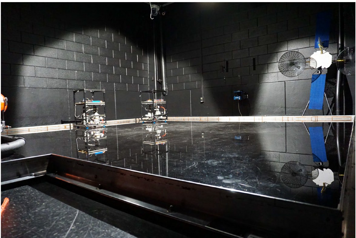
The two COSMOS sleds in the test arena.
ASTROS reproduces the motion of a single spacecraft in five degrees of freedom. COSMOS answers the
complementary question: what happens when there is more than one. Two free-floating platforms share
the arena, so relative motion, rendezvous and proximity operations can be studied between vehicles
that are both under their own control, rather than between one active vehicle and a fixed target.
A COSMOS platform.
Each platform behaves like a floating sled with three degrees of freedom, two translational and one
rotational. Four air bearings beneath the frame levitate it on pressurized air, and eight cold-gas
thrusters, positioned to be most efficient in the plane, provide the forces and torques that move it.
A reaction wheel is projected to control orientation by momentum exchange, sparing the thrusters for
translation.
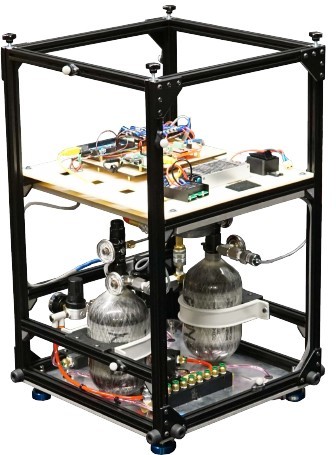
Three tanks store air at 3000 psig and feed the thrusters and bearings through two pressure
regulators and heavy-duty pneumatic hoses. Every thruster and bearing carries both a manual ball
valve and a solenoid, the latter opened and closed by a pulse-width-modulated signal from an onboard
Arduino. A three-cell lithium-polymer battery supplies a nominal 11.1 V through two electrically
isolated DC/DC converters: 12 V for the thrusters and the reaction wheel, 5 V for the onboard
computer, the IMU and the pressure transducers.
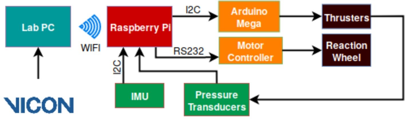
A Raspberry Pi on each sled receives commands from the lab PC over WiFi, drives the thruster Arduino
over I2C and the reaction-wheel motor controller over RS-232, and reads the IMU and the pressure
transducers. Ground-truth position and attitude come from the arena's Vicon motion-capture system.
COSMOS system architecture.
Specifications
Platforms
Two free-floating sleds, operated together for multi-spacecraft experiments
Degrees of freedom
Three per sled — two translational and one rotational, in the plane
Flotation
Four air bearings beneath each platform
Thrusters
Eight pressurized-air thrusters, positioned to maximise efficiency in producing planar motion
Momentum exchange
A reaction wheel controls orientation (projected)
Air storage
Three gas tanks at 3000 psig, fed to the thrusters and bearings through two pressure regulators
Valves
Each thruster and bearing has a manual ball valve and a solenoid, driven by a PWM signal from an Arduino Mega
Power
Three-cell LiPo at a nominal 11.1 V, through two electrically isolated DC/DC converters: 12 V for the thrusters and reaction wheel, 5 V for the computer, IMU and pressure transducers
Onboard computing
Raspberry Pi, linked to the lab PC over WiFi, commanding the thruster Arduino over I2C and the reaction-wheel motor controller over RS-232
Sensing
IMU over I2C for linear acceleration and angular rate, pressure transducers on the pneumatic system, and external Vicon motion capture
An open platform for aggressive autonomous driving
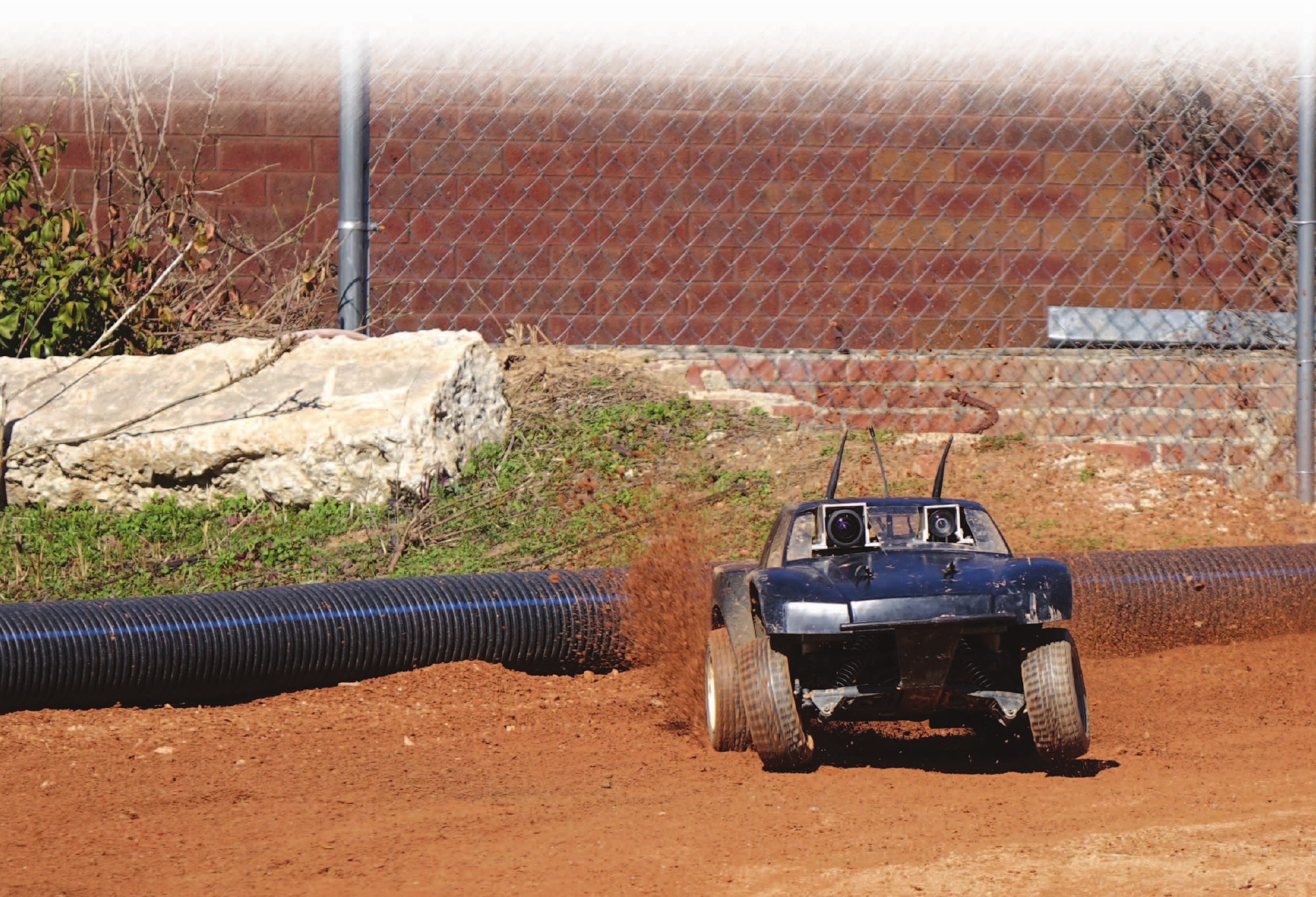
An AutoRally platform at the Georgia Tech Autonomous Racing Facility.
Aggressive driving — drifting, high-speed cornering, recovering from a slide — takes a vehicle into
regions of its state space that normal driving never visits, and those are exactly the regions an
autonomous vehicle must handle when something goes wrong. Testing there with a full-size car is
expensive and dangerous, and simulation alone cannot capture tire and terrain behaviour at the
friction limit. AutoRally is the compromise: a vehicle small enough to crash without consequence and
large enough to carry real sensing and computing.
The platform is a 1:5-scale robot about a metre long, weighing 22 kg, with a top speed of 90 km/h.
It is robust enough to be driven at its limits repeatedly, yet simple enough for two people to
maintain and operate. A fleet of six has driven hundreds of kilometres autonomously at the Georgia
Tech Autonomous Racing Facility, and the design is open: build instructions, a parts list, CAD models
for the custom components, a Gazebo simulation environment and datasets published as ROS bag files
are all available, with the software programmable in C++ or Python under ROS.
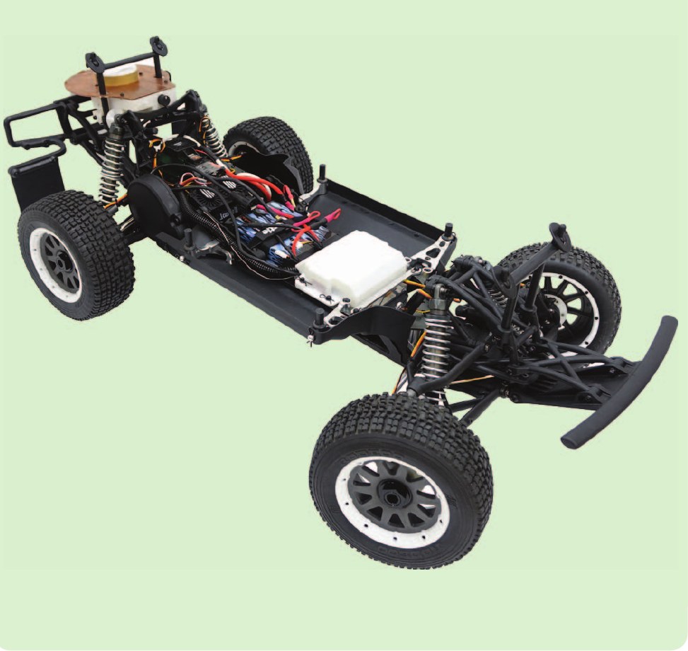
The assembled chassis.
The vehicle divides into a chassis and a compute box. The chassis is a modified RC platform whose
steering linkage and side rails were replaced with billet aluminium to carry the extra weight, with
stiffer springs and heavier shock oil to match. The compute box is a sealed mini-ITX enclosure that
mounts inside the stock body, deliberately built from standard parts rather than embedded hardware so
that algorithms developed on a desktop run unchanged on the vehicle.
Sensing is chosen for the off-road, high-speed regime: GPS with real-time kinematic corrections for
absolute position, an inertial measurement unit at 200 Hz, a pair of global-shutter cameras triggered
together, and Hall-effect wheel-speed sensors on every hub. Because the human control signals are
read and logged even under manual driving, the platform also collects the expert demonstrations that
learning-based controllers need.
Specifications
Scale
1:5, about 1 m long and 22 kg, with a top speed of 90 km/h
Chassis
Modified RC chassis with billet aluminium steering and side-rail parts, stiffer springs and heavier shock oil to carry the sensing and computing payload
Computing
Mini-ITX compute box with an Intel i7-6700 quad-core at 3.4 GHz and an Nvidia GTX-750ti with 640 cores
Positioning
Hemisphere P307 GPS at 20 Hz, accurate to roughly 2 cm with real-time kinematic corrections from a base station
Inertial sensing
Lord Microstrain 3DM-GX4-25 IMU at 200 Hz, up to 1 kHz raw
Vision
Two Point Grey Flea3 global-shutter colour cameras, up to 60 Hz, triggered together for stereo
Wheel speed
Hall-effect sensor and magnets on each wheel hub, timed by the onboard Arduino Due and reported at 70 Hz
Software
ROS, programmable in C++ or Python, with a Gazebo simulation environment and public datasets as ROS bag files
Fleet
Six platforms at Georgia Tech, which have driven hundreds of kilometres autonomously at the Georgia Tech Autonomous Racing Facility
Goldfain, B., Drews, P., You, C. Barulic, M., Velev, O. Tsiotras, P., Rehg, J. M., “AutoRally: An Open Platform for Aggressive Autonomous Driving,” IEEE Control Systems Magazine, Vol. 39, No. 1, pp. 26–55, 2019.
This facility was made possible through an ONR DURIP award.
Collaboration
AutoRally was developed jointly at Georgia Tech with the groups of James M. Rehg and Evangelos
Theodorou. The platform is open source and documented at
autorally.github.io.
BuzzRacer
A palm-sized platform for multi-agent adversarial decision-making
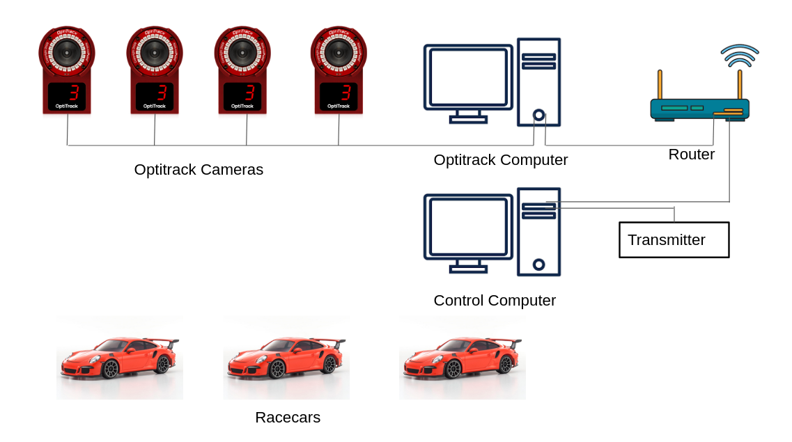
The BuzzRacer testbed: motion capture, an off-board control computer, and the vehicles.
Autonomous racing asks a controller to operate an underactuated, nonlinear vehicle near the limits of
its grip, close to the track boundary, against opponents whose intentions are unknown — and to do it
in real time. Experiments of that kind are rare, because the platforms are expensive and the space
they need is large. BuzzRacer attacks both constraints by shrinking the car.
Each vehicle is 1:28 scale, 165 by 80 by 40 mm, and weighs 170 g — only four grams more than the
stock chassis it is built on, so it keeps the handling of the original. It reaches 3.5 m/s and pulls
1 g laterally, which puts genuine limit behaviour inside a room rather than a field. Computation
stays off board: the vehicles receive commands and report sensor measurements over WiFi, so an
algorithm too heavy for embedded hardware can still be tested on real cars, and several vehicles can
run against each other at once.
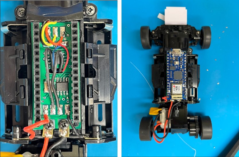
The replacement PCB, and the vehicle without its body shell.
The stock electronics are replaced by a custom board carrying an Arduino Nano 33 IoT, which brings a
WiFi radio and a six-axis IMU, and drives the motor and steering servo directly. That last point
matters more than it sounds: a hobby servo takes about a tenth of a second to move sixty degrees, and
its own closed-loop controller is a black box, so at racing speeds the steering dynamics are not
negligible. Here the servo loop is closed in the platform's own firmware against the measured angle,
which makes the vehicle model accurate enough to control against.
The software stack is configuration-driven: an XML file names the modules to load and the parameters
to set, so the same controller runs in simulation or on hardware by changing one field. Simulation
uses a single-track dynamic bicycle model whose parameters were identified from the real vehicle,
and tracks are assembled from straight and turn elements, or given directly as a centreline and
width. BuzzRacer is open source and is used at Georgia Tech both for research and in a project-based
robotics course.
Specifications
Scale
1:28, palm-sized at 165 x 80 x 40 mm and 170 g, only 4 g heavier than the base chassis
Performance
1 g lateral acceleration and 3.5 m/s top speed
Chassis
Kyosho Mini-Z rear-wheel-drive chassis, widely available and inexpensive to replace
Onboard electronics
Custom replacement PCB carrying an Arduino Nano 33 IoT: SAMD21 Cortex-M0 at 48 MHz, u-blox NINA WiFi and Bluetooth radio, and a six-axis IMU
Actuation
Two 15 kHz PWM pairs for drive and steering; the steering servo is closed by a 500 Hz PID loop on measured angle rather than the stock black-box controller
Communication
Lightweight UDP protocol with fixed 64-byte packets over WiFi, at 100 Hz
Localisation
Optitrack or Vicon visual tracking, with an extended Kalman filter for state derivatives
Simulation
Single-track dynamic bicycle model with parameters identified by unscented Kalman filtering; artificial noise can be injected to test robustness
Tracks
Grid-style layouts assembled from straight and turn elements in a single line of code, or arbitrary tracks from a centreline and width
Zhang, Z., and Tsiotras, P., “BuzzRacer: A Palm-sized Autonomous Vehicle Platform for Testing Multi-Agent Adversarial Decision-Making,” IEEE/RSJ International Conference on Intelligent Robots and Systems, Abu Dhabi, UAE, Oct. 13-17, 2024, pp. 8510-8515.